Roland CR-78 MIDI Clock Mod
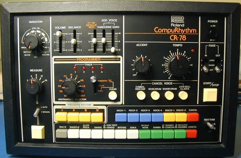
Someone recently suggested that I investigate adding MIDI clocking to the Roland CR-78 CompuRhythm drum machine. Other desired features were a way to trigger drum sounds using MIDI note messages, and a way to edit user programs as with the WS-1, but using the front panel controls. Other people/companies have made add-ons for the CR-78, but they tend to require lots of wires to be connected into the CR-78 circuitry. I thought that replacing the MCU should enable new features without requiring a lot of additional wires. As it turns out, two wires did need to be added to control signals that the MCU does not have access to, but that was all.
The first step was to read out the firmware in the CR-78's 8048 MCU, and also in the 2708 EPROM, then study this code to understand how it worked. As usual, I made a simulation of the CR-78 so I could watch the internal workings. The next step was to convert the 8048 assembly code to equivalent PIC assembly and test/debug it. Once I had a fully working MCU replacement, it was time to think about how to incorporate the new features into the existing code structure without breaking anything or affecting normal operation.
One part of adding new features to an existing design is figuring out how to control these features with the existing knobs and switches as intuitively as possible. One example of this was figuring out how to mimic the operation of the WS-1 without having any additional switches. Luckily, the variation switches were free when editing user programs, and could provide the needed functions. Another example was needing a way to enable the MIDI module or User Program Edit modes. Since the CR-78 only supports playing two built-in rhythms together, pressing three rhythm switches at once seemed like a reasonable way to enable these modes.
I am now offering (for $100 plus shipping) an MCU replacement for the CR-78 which offers the following new features:
1) MIDI clocking of rhythms using MIDI Start, Clock and Stop. Ratio is fixed at 24 PPQ. (96 pulses per measure)
2) MIDI module mode, in which specific notes trigger specific drum sounds. Velocity above 64 triggers the accent. MIDI channels 1-11 can be selected.
3) 15 User programs, stored in EEPROM (The two RAM chips are no longer used)
4) User program editing using the WS-1 method, but without needing a WS-1.
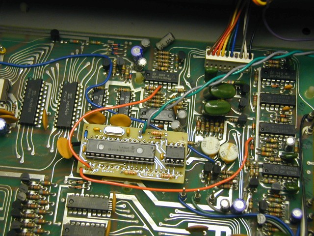
Here is how the first version of the pcb looks after installation: (The green and gray wires connect to the MIDI IN jack)
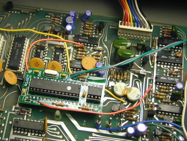
And here is the production version of the pcb:
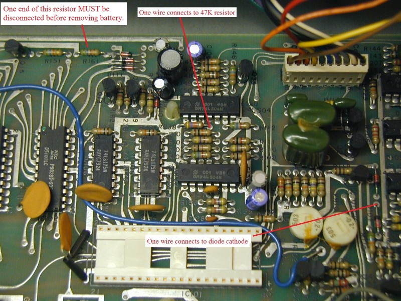
The battery has been removed from the above unit, as it is no longer used. This requires first either cutting or lifting one end of R161 (5.6K) which can be seen near the top edge of the pcb in the photo, standing up off of the board.
Here is a better photo showing this, and also the mod wire connection points:
Here are the instructions for installing the upgrade, and here are the instructions for using the new features.
What about the CR-68?
Please contact me if you are planning on installing the mod in a CR-68, as I have some additional information that is not presented here.
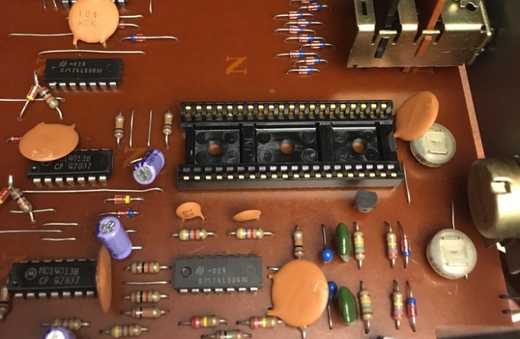
The CR-68 and CR-78 both use the same 8048 MCU, with the same internal firmware. The extra code that the CR-78 needs to access the external SRAM containing user rhythms is located in a separate 2708 EPROM. This code is only used when a program switch is pressed, and since these switches do not exist on the CR-68, it never tries to execute this code or access the external SRAM chips of the CR-78. What this means is that my MCU replacement is also compatible with the CR-68, but the user rhythms will not be accessible. MIDI clocking and the MIDI module mode will work as in the CR-78. Unfortunately, the type of IC socket used for the MCU in the CR-68, at least in the one unit I have seen, is not compatible with the DIP header used in my design. The header hits the side walls of the socket, preventing it from plugging in all the way. It won't make good connections, in fact it won't even stay in place. Here is the MCU IC socket used in the CR-68:
To install the MCU replacement in a CR-68, you must remove this IC socket, and replace it with a more standard "dual wipe" type which has contacts on either side of the IC pins. Of course, if your CR-68 has a different type of IC socket for the MCU, then this modification may not be necessary. Two other issues have also been observed when the module was installed in a CR-68:
a) Noise glitches on the two clocks to the 74LS175's that trigger the drum sounds were clocking garbage into these chips. I added 470 pF capacitors at the 74LS175 chips IC2 and IC3 from pin 9 to pin 8 (gnd) to fix this.
b) The IC4 chip that drives the Manual Variation switch when the CPU wants to read it was not driving it low enough. I added a BAT48 shottky diode in parallel with D209 to fix this.
Important Warning:
The battery in the CR-78 acts like a zener diode to limit the supply voltage to the SRAM chips. If you want to remove the battery, or replace it with a lithium type, you must first cut or remove R161, or the SRAM chips will be damaged from excessive voltage.
I will not be responsible for damage to any instrument caused by either proper or improper use of the
information presented here.