WWVB Chiming Clock Kit
Features:
- Selectable clock type: Westminster chime #1 or #2, grandfather clock, cuckoo clock, shelf clock, ship's bell clock
- Synchronizes with WWVB at midnight to maintain very accurate time
- Automatically adjusts for Daylight Saving Time, on next sync after time change
- Chime and tick-tock volume independently adjustable for each clock type
- Announce mode speaks the time every 5,10,15, or 30 minutes
- Sound can be muted at night (10PM-8AM) if desired
- LED's indicate result of last WWVB sync
- Super capacitor keeps time for several days if power is lost
- No display is needed - spoken feedback is provided during setup
- Settings stored in non-volatile EEPROM memory
- Uses a standard 9VDC wall adapter (either polarity, not included)
- Works with standard computer-type AC adaptor-powered speakers (not included)
This is the third major revision of a design which I have been refining for a number of years.
Note: This clock needs the WWVB signal to work properly. It will not work correctly outside of the USA.
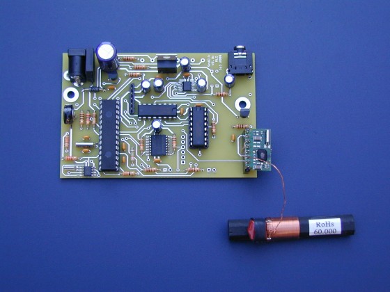
Above photo shows a populated WWVB chiming clock pc board with a WWVB receiver module and its ferrite rod antenna connected. Six eyelets at the top of the board connect to three pushbutton switches for selecting clock type, time zone (USA only), etc. Four eyelets near bottom edge are for green and red LED's to indicate WWVB reception status. DC power jack is shown in upper left corner. 1/8" stereo audio jack is in upper right. (Clock output is mono, fed to both channels) SMT RTC chip in lower left corner keeps accurate time between syncs and during power loss. SMT serial flash chip (bottom center) holds all waveforms. TI audio DAC is small SMT chip closest to audio jack. PIC chip (28-pin DIP) controls all activities.
Here's how it looks installed in a simple Radio Shack (#270-1806) plastic enclosure:
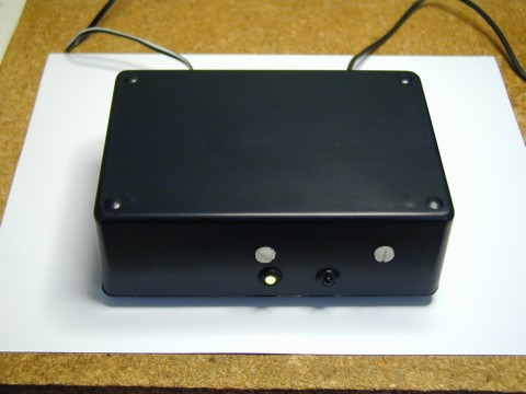 Left
(green) LED is on, indicating that the most recent WWVB synchronization attempt was
successful and the clock is within a second of the correct
time. Nylon screws are used to fasten the internal WWVB
ferrite rod antenna without affecting it, as metal screws would.
The antenna cannot be inside a metal case, and must be at least 1"
from any metal, so a plastic or wooden case should be used. (Note: No enclosure is supplied. Others could be
used.)
Left
(green) LED is on, indicating that the most recent WWVB synchronization attempt was
successful and the clock is within a second of the correct
time. Nylon screws are used to fasten the internal WWVB
ferrite rod antenna without affecting it, as metal screws would.
The antenna cannot be inside a metal case, and must be at least 1"
from any metal, so a plastic or wooden case should be used. (Note: No enclosure is supplied. Others could be
used.)
Green plug connects audio output to powered speaker(s) Other cable is 9VDC power from wall transformer:
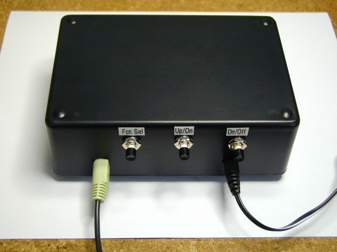
Left switch selects function to be set/adjusted, and the other two switches change that setting. Spoken feedback of function and setting is provided. Functions are:
- Clock type selection
- Tick-tock sound on/off
- Muting at night (10PM-8AM) on/off
- Strike volume adjustment (stored separately for each clock type)
- Tick-tock volume adjustment (stored separately for each clock type)
- Time zone selection (Four USA time zones only)
- Hour time set
- Minute time set
- Daylight Saving Time observance - on/off
- Announce (speak time every 5/10/15 or 30 minutes) on/off
Unfortunately, several of the parts used in the WWVB clock are only available in SMT packages and will require good soldering skills. The TI DAC pins have fairly fine pitch, so if you haven't soldered this type of chip before, you may not want to attempt it. (I use a microscope and a fine-tipped soldering station.) (The clock draws about 35 mA from the 9V adapter.)
Note: This clock relies on the WWVB signal for accurate timekeeping. Although it may work without the signal, I don't recommend using it this way. Also, the time zone can only be set to the four zones in the Continental USA.
Price (not including small per-order S&H fee):
WWVB Clock Kit - $TBD
Includes clock bare pcb, programmed PIC microcontroller, programmed
Flash memory chip, WWVB module, and WWVB ferrite bar
antenna. All other electronic parts necessary to assemble
the board are available at Digikey. DAC and RTC chips have small
pins and require good SMT soldering skills to install. Flash chip
is also SMT. Please download assembly
instructions, schematic page
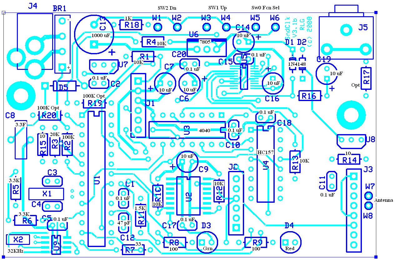
1 and page 2, parts
list, parts placement, and operating instructions.
DISCLAIMER: I take no responsibility whatsoever for the use and/or implementation thereof, or the misuse leading to damage to equipment, property, or life, caused by the above circuits.