Rhodes Chroma Dual Channel Board Tester
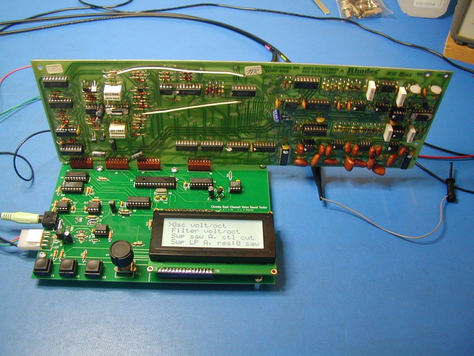
I have been thinking for several years that I would like to design a test fixture for Chroma voice boards, to allow stand-alone testing with easy access to the circuitry. Initially I was planning to have the tester automatically run through a number of tests and give an overall pass/fail result. But I decided it would be better to offer tests that would be helpful in evaluating a board, and let the user make the decisions. In addition to the tests, I implemented a full manual mode, with control over all parameters. The tester requires +/- 12.0 volts DC, well regulated as these voltages power the voice board. Current limiting would be nice, if possible. The tester and voice board together draw less than 150 mA from either supply.
While listening to the output during some of these tests may be useful, most were designed with oscilloscope testing in mind. A trigger signal is provided to allow synchronizing an oscilloscope to the test sweep. Best results will be obtained with a digital sampling oscilloscope. The audio output signal is available for probing on the tester pcb, and an 1/8" jack is provided for it as well. The S&H tests require probing op amp outputs on the voice board.
The following tests are currently implemented:
1) Oscillator and filter A/B tunability test
2) Oscillator A/B volts/octave measurement
3) LP Filter A/B volts/octave measurement
4) Osc A/B saw frequency sweep with control of filter cutoff
5) Filter A/B LP filter frequency sweep with control of resonance
6) Filter A/B HP filter frequency sweep with control of resonance
7) Oscillator A/B PW sweep, pulse or saw waveform
8) VCA A/B sweep with saw oscillator running
9) Oscillator sync mode with control of oscillator B frequency
10) Oscillator ring mod with control of oscillator B frequency
11) Filter FM mod with control of oscillator B frequency
12) S & H two second drift test - stop refreshing and monitor control voltages
13) S & H update speed test - pulse all 8 control voltages in slow and fast modes
This is not a test, but is in the test menu:
14) Switch to Manual mode, default initial settings
Manual Mode offers individual control of these parameters: (via a menu and an encoder)
1) Osc A/B waveform selection (white and pink noise inputs fed with constant tones)
2) Osc A/B Pitch
3) Osc A/B Pulse Width
4) Filter A/B Cutoff frequency
5) Filter A/B Resonance
6) Channel A/B Volume
7) Filter A/B Mode
8) Cross Mod
9) Patch
10) Oscillator Enable
11) Output channel
These are not parameters, but are in the Manual mode menu:
12) Load Preset A
13) Load Preset B
14) Save as Preset A
15) Save as Preset B
16) Switch to Test mode
Here are scope photos showing several tests being run.
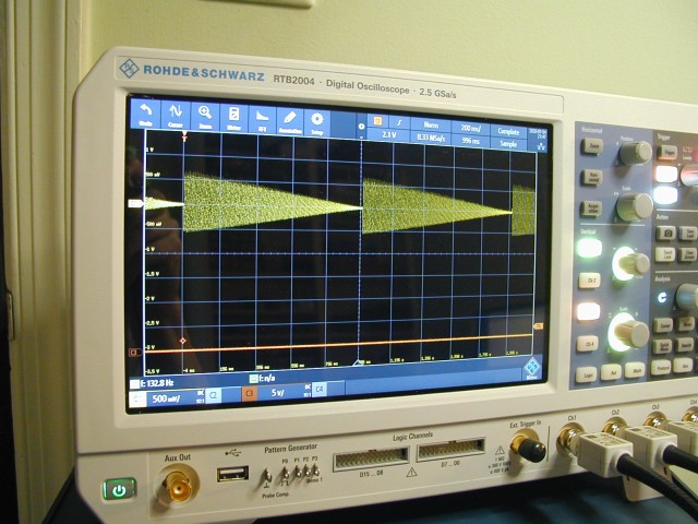
This shows the output signal with the A channel VCA control voltage being swept twice a second. The bottom trace is the trigger signal.
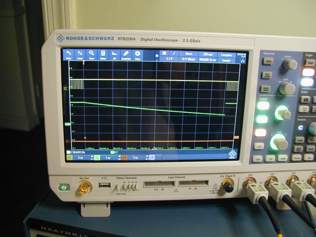
This shows the pitch A CV (probed on the voice board) discharging when S&H updates are temporarily stopped. A 66M resistance was added to ground across the hold capacitor to simulate leakage. The yellow trace is the enable for the S&H chips.
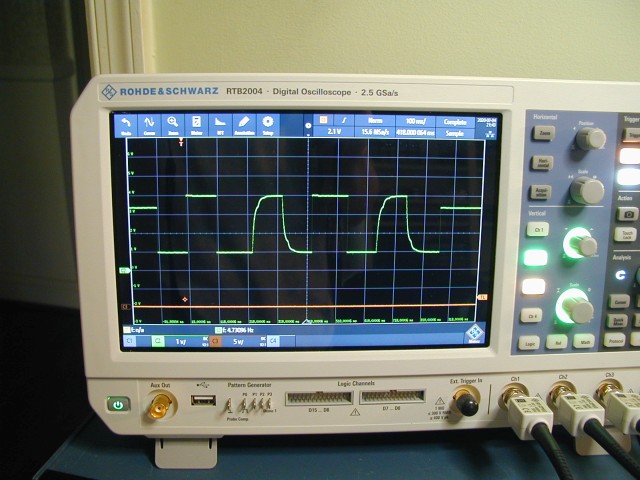
This shows the pitch A CV (probed on the voice board) being switched from 1V to 4V rapidly. Fast updates are only enabled on the first and third pulses.
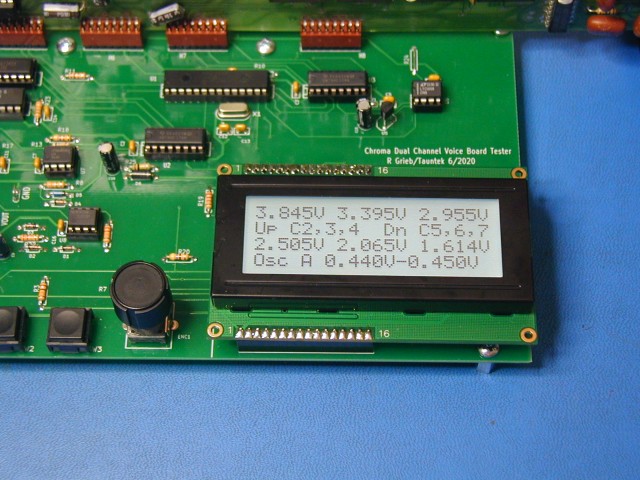
This shows the results of the Osc A volts/octave test. The MCU measures the CV required to tune to C2,C3,C4,C5,C6 and C7 notes and displays them. Then it calculates the minimum and maximum difference between these voltages and displays that. Note that the oscillator frequency increases as the control voltage is decreased.
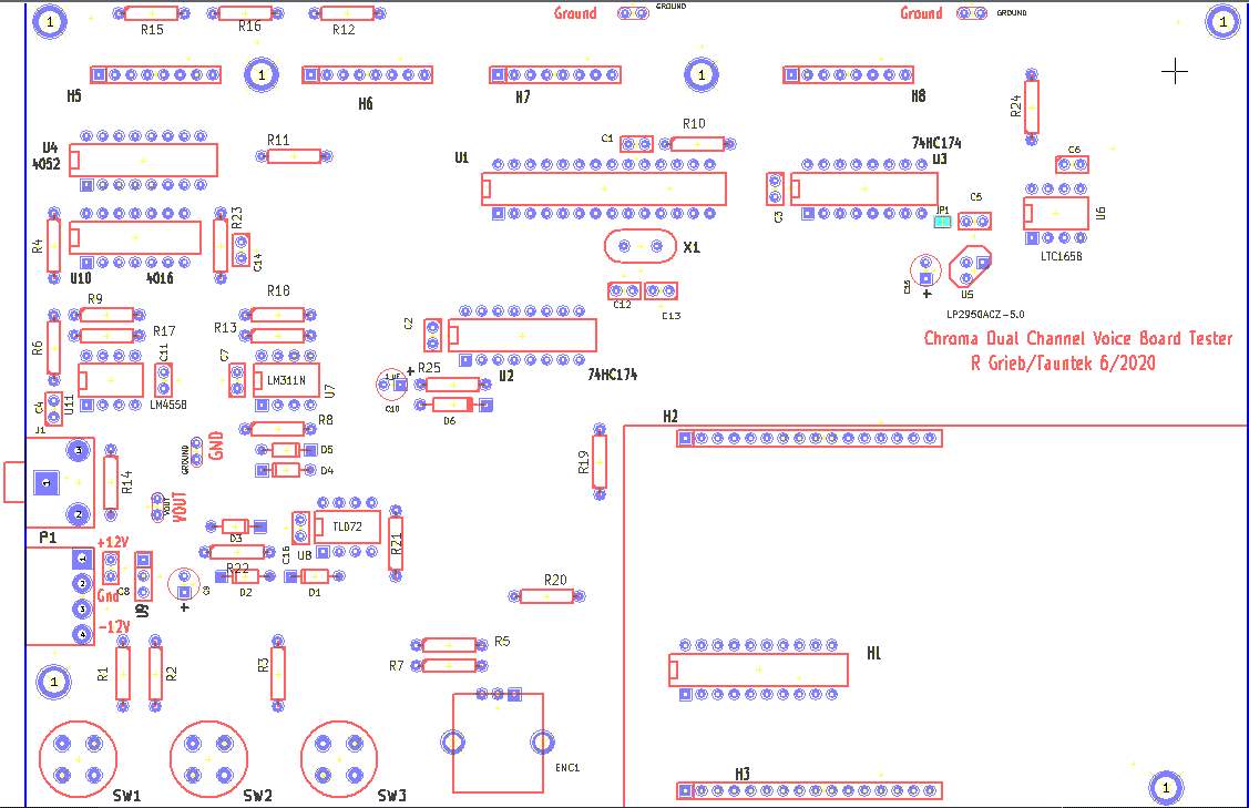
I am currently offering bare pc boards for $30 plus shipping and programmed PIC chips ($10) if anyone wants to build one of these. Here is a parts list for the other components. Here is some important information about assembling the pcb. Here is similar information for version 1.1 of the pcb. Here is the schematic for current V1.1 of the pcb. Here is a component placement dwg for the pcb. Here is the schematic for the older V1.0 pcb.
Here is a short User Manual for the tester. Please feel free to email me if you feel more information is needed in some places.
Here is an archive containing a hex file for the PIC code, along with the configuration bits data. With many programmers, this data needs to be entered manually before programming the chip.
About firmware updates:
If you purchase a programmed PIC from me, you are buying the current version of the firmware. If I make changes in the future, I will update the hex file posted here, but I am not able to send out free updates. At this time, I am happy with the code and do not plan to add any new features as I am busy with other projects. If someone finds a genuine bug, then I will try to fix it, and update the image posted here.