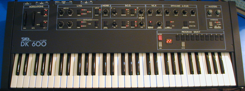
Siel DK 600 1980's Six Voice Analog Synthesizer
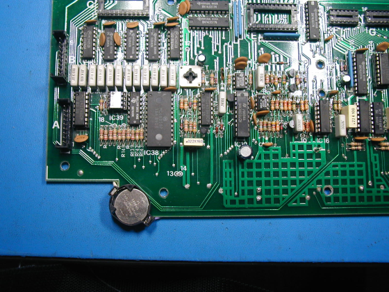
I recently purchased three DK 600's in non-working condition. All three had the usual circuit board damage from battery leakage. I picked the CPU board with the least damage and started replacing components in the "blast zone" as it is called in SoundDoctorin's entertaining and informative youtube videos on repairing this synth. A number of resistors and two IC's had to go, along with several transistors and diodes. Luckily, no traces were eaten through, just a lot of crusty solder joints, corroded component leads, and crud on the board. I didn't replace the transistors at first, only after troubleshooting revealed that they were not working. Once all of the obvious battery leak damage was addressed, I checked and adjusted the power supply voltages and the synth started to work. No patch data in RAM, but just getting sounds was encouraging.
The DK 600 only sends the current patch to MIDI as a sysex packet. The Siel code does not support dumping all of the patches in one operation. My units had EPROMs containing versions 7 and 8 of the firmware, and a friend had a unit with version 9, so I ran all three of them through a TMS7000 disassembler and started looking at the code. Version 7 does not support setting a MIDI channel and disabling OMNI mode. Version 8 added those features, and has many differences from version 7. Version 9 is almost identical to version 8. It fixes a bug having to do with handling CC's for enabling and disabling OMNI mode via MIDI. (I suspect that feature would not work in version 8, and might cause the synth to crash if one of those messages is received) I added some code to the V9 firmware to use preset 99 to transmit presets 0-94 as individual sysex packets. The DK 600 can accept a MIDI sysex packet to load a specific preset, but requires a special CC to be received before each sysex packet. The three hex bytes Bn 57 7F must be received before each sysex preset packet (n is the current MIDI channel). In my code to dump all of the presets, I added the sequence B0 57 7F before each preset's sysex packet, so the resulting transmission includes everything you would need to send back to the DK 600 to load the presets. Unfortunately, you cannot use MIDIOX to capture the dumped data, as it will strip out the CC messages, since they are not sysex. Instead, I used a PC program called MIDITools, which works well and allowed me to capture all of the bytes and save them to a file. I am sure there are other programs that could also be used for this. Since the CC is set up for MIDI channel 1, to load patches into a DK 600, it must either be in OMNI mode, or set to MIDI channel 1. Also, the MIDI EXT LED must be on. You should see the display count from 00 to 94 as the presets are loaded.
Once I had a way to save the presets using MIDI, I started looking on the web for a wave or sysex file of the factory presets and found both. The sysex file did not include presets 90-94 which are used in the calibration procedure, so I tried loading the wave file using the cassette interface. I found that at the end of the wave file, the Enter LED would always blink and the INT/FROM LED would always go out. But if I then dumped the RAM preset data using the new firmware, it was different each time. I found that if I loaded the web sysex file instead and then dumped the presets, my dump matched the web file's data exactly. And if I did a tape load, then dumped the presets to MIDI twice, the two dumps would match exactly. So it seemed that my code was working, but that the tape load was not 100% reliable. I tried many settings of volume and tone and got fewer mismatch errors between different loads, but never less than about 50 errors, and often many more. While this may sound like a lot of errors, the preset data takes 1900 bytes, or 15,200 bits. Most of the errors were just one bit wrong in a particular byte. In any given patch, some of the data is not used, for instance the pulse width setting if pulse wave is not enabled. So it's possible to have a lot more than 50 errors with little effect on the presets, if they are located in the right places. By the way, the DK 600 does not save any sort of checksum or CRC with the preset data, so it has no way to determine if the tape load was error-free. Also, as I discovered later, the DK 600 does not use Frequency Shift Keying (FSK), which was the standard way of storing digital data on cassette tape used by computers and synths in the late 70's and early 80's. Instead, some form of pulse width encoding was used, which seems to be much less reliable and more error-prone. I ended up writing a small Verilog program to extract the factory presets from the tape waveform data. I also purchased a DK 600 factory cassette, and using a portable cassette recorder to play it into the DK 600, was able to get a MIDI dump of it to match the data generated by the Verilog program exactly. This required a lot of fiddling with the volume setting on the tape recorder. And right after I got a successful tape load, I tried another one and got a bunch of errors. Also, my sysex dump of what I think is the correct factory preset data does not match the web sysex file exactly. This makes sense, as that file must have been generated by loading a tape, then dumping each preset one at a time. The DK 600 has a tape "verify" feature. But since there is no checksum or CRC in the data, even if a verify "passes" and every byte matches, it doesn't guarantee the data is correct. It only means the tape loaded the same way twice. While I can't be sure my preset data is 100% correct, I think there is a good chance that it is. Also, the presets used for calibration do seem to have the correct settings. Preset 91 puts the filter in resonance, and preset 92 sets the attack to the maximum value.
Once I had a way to load presets, I decided it was time to install some sort of battery. I wanted to use a CR2032 3V lithium if possible, so it could mount on the pc board. Didn't want to mess with a rechargeable battery. To use a non-rechargeable battery, you would replace the 220 ohm R25 resistor that is in series with the battery with a 1N4148 diode to prevent charging, which could damage the battery. The anode of the diode should be connected to the battery positive. Before committing to the 2032, I measured the "off" current using a 3V bench supply and a current meter. The value was 13.5 uA A quick calculation indicated that a 2032 would only last about 1.5 years at that rate. Disappointing. I started wondering if the RAM was really drawing that much current, so I removed it from the socket. The current was still about 13 uA! The battery only connects to a few things, so it was easy to remove all of them, and the current was still around 13 uA. Turns out that by cleaning the board really well in this area with cue tips and isopropyl, I was able to reduce the current to about 0.3 uA, with the RAM and the other components back in place. At that value a 2032 will last many years. I wanted to use a battery holder, but didn't want to mount it where the old battery had been, in case more cleaning or repairs were necessary in the future. I ended up putting the holder on a front corner of the board, fastened with double-stick foam. This way I did not have to drill any holes in the board, and I can move it later if I decide to.
One note about removing the NiCAD battery: Since the voltage across the battery will never exceed about 3.6volts, there is always some current through R25 which acts to pull down on the 5V supply to the SRAM chip during normal operation. If you replace the resistor with a diode, as when using a lithium battery, there is no longer any current pulling down on the +5V supply to the SRAM chip, and the output of IC11 can pull it up through transistor T3 to a level higher than 5 volts. Someone recently emailed me about this and had measured 5.6 volts at the supply pin of the SRAM chip when the synth was turned on. While it's not a sure thing that 5.6V is a problem, the voltage could go even higher, limited by the protection diodes in the SRAM chip. His solution was to add a diode between the junction of R23 and R24 and the +5V power supply, with the anode connected to the resistors. A simple 1N4148 silicon diode would be fine here. I have not installed this diode on my DK 600, but may in the future.
Versions 8 and 9 of the Siel firmware support setting the MIDI channel. To do this, select preset 96, hit Enter. The display will show the current value. Now enter a two-digit code (00-15) for MIDI channels 1-16 and hit Enter. Doing this will also disable OMNI mode. The MIDI channel and the current dynamics setting (0-3) are saved in RAM which is preserved when power is turned off. But for some reason the OMNI mode setting was not saved, and OMNI is always enabled at power up. So even though setting the MIDI channel disables OMNI mode, if you turn the synth off, then back on, it will revert to OMNI mode. I added some code to save the OMNI setting at power off and restore it at power on. The Siel code ignored invalid MIDI channel entry. I decided to change the entered MIDI channel range to 01-16 in the new code. The value 00 is entered to enable OMNI mode. This will also set the MIDI channel to 1, although it won't be used until a new channel is entered to disable OMNI mode. Any entered MIDI channel number higher than 16 will be ignored.
The +5V supply measured 4.84V on the digital board, so I decided to increase it a little. Siel did not provide any adjustment for this voltage. Rather than install a trimmer, I just replaced power supply R7 180 ohms with a 200 ohm 1/4W 5% resistor. This gave me 4.95 volts across the pins of one of the code EPROM chips, which seemed close enough to me.
Here is an archive containing a sysex file which hopefully accurately represents Opera 6/DK 600 factory presets 0-94, so this includes the presets used for calibration.
Here is an archive containing a sysex file which has only factory presets 90-94. These are the ones used during calibration. By loading this file you can have these presets for performing the calibration without losing the rest of your patches.
Here is an archive containing the three different versions of Siel Opera 6/DK 600 firmware mentioned on this page.
And here is an archive containing my V10 firmware, based on "OP6-09" with the changes mentioned above. This is the first version I created, before I added CC support.
Even Newer Firmware:
I now have a version of the firmware which supports modifying parameters using MIDI CC's. If you are able to program 2532's (many programmers will not program them, so please check first) and want to try this firmware, please contact me. I don't want to put the code here, as I don't want it showing up on ebay for sale.
Here is information on the CC numbers supported in the new firmware.
Here is an archive containing a template that someone has generated for the BCR-2000 to work with the new DK 600 firmware that supports CC's. I do not have a BCR-2000, and have not tested this myself.
Please note: Taking a DK600 apart and replacing chips must be done carefully, or damage to the synthesizer could result. It should only be attempted by someone familiar with this type of work. I will not be responsible for any damage to any instrument caused by either proper or improper use of the information offered here.