GenRad 1657 RLC Digibridge
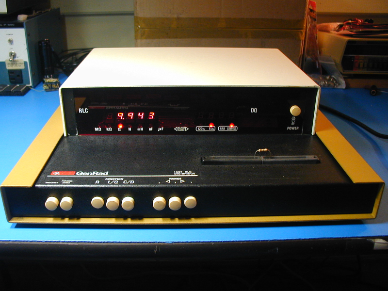
Lately I have been working a lot on 1980's analog music synthesizers, which rely on accurate and stable resistors and capacitors for proper operation. I decided it would be nice to have a more accurate way to evaluate these components than a simple DMM, so when the above unit appeared for sale (not working), I decided to grab it. Although this unit is from the late 70's, it is quite accurate and still useful.
The 1657 design was novel in its simplicity and inherent accuracy, and was patented (#4,196,475). Earlier impedance bridges required precise capacitors and inductors, which were used in a bridge configuration to create a balance against the device being measured. Then the dials could be read to determine the measured value. The 1657 uses a completely different approach. A sine wave is applied to the measured device and a precise resistance in series. The average voltage across each device is then measured using four different phases relative to the input sine wave, for a total of eight measurements. From these, the resistive and reactive components of the tested device can be calculated and displayed.
The 1657 uses a 6503 CPU, which is a 28-pin version of the 6502 with the same instruction set, but fewer address lines. The code resides in a 2Kx8 ROM chip, which was later replaced with a 2716 (but not in my unit). A 128-byte SRAM is used for scratch pad and the stack. The logic is a mix of 74LS, op amps, and 4000-series chips, presumably to reduce power consumption. My unit had two bad CA3600E chips. Luckily, this obsolete part is equivalent to a CD4007UB. All of the chips are socketed, and quality components were used, although pretty much every 1/4W 5% carbon composition resistor that I measured was about 10-15% high, so I replaced the ones that were not just pull-ups. One indication of the elegance of this design: there is not a single trim pot in the unit! Nothing to calibrate.
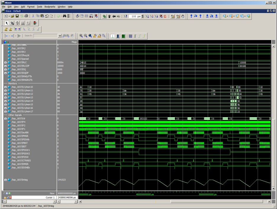
I decided to read out the 2Kx8 code ROM, in case anyone needs it for a repair. The pinout is totally non-standard, so I made a little adapter to make it look like a 2716. Of course once I had the file, I couldn't resist running it through a disassember and trying to see what I could learn about how it worked. And since I was doing that... I ended up creating a Verilog simulation of the 1657, with a 6502 CPU model running the code that I had read, and a very simplistic model of the analog front-end. When I simulate the correct analog values for a 10 ohm resistor being measured, the RLC display measures 10.000 (visible as "10000" in the top right of the waveforms). Below are some waveforms from about 1/2 second of simulated time. At the bottom you can see the integrator output waveform. This is a dual-slope integrator, combined with a 19-bit counter to make an accurate A/D converter. Eight different measurements are required to calculate the parameters of the part being tested.
In case anyone needs a binary image of the code ROM/EPROM, or wants to look at my assembly source file, which includes some comments explaining what some of the code is doing, here they are. My source file is valid input to the TASM32 assembler, and generates a binary output that is identical to the one I read from the ROM in the 1657.