Replacing Oberheim Matrix Six VFD With a Std LCD Module
I wrote a small PIC program to map the serial data sequences used in the Matrix 6/6R to a standard 1x16 LCD module. Five wires are required to connect the replacement display to a Matrix 6/6R:
VCC (+5V), GND, DCLKb, DCLRb, and DDATA
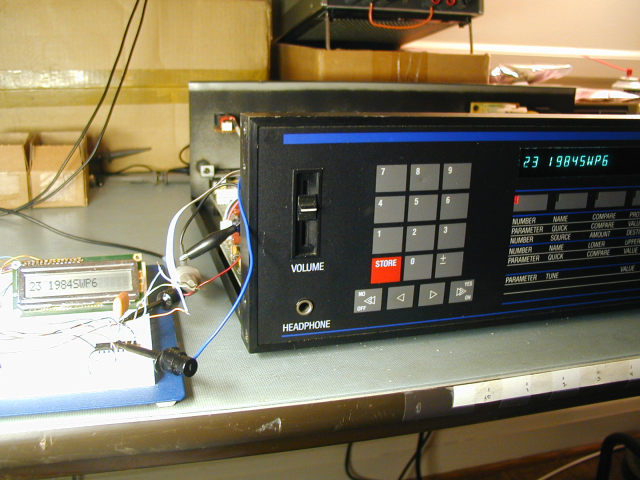
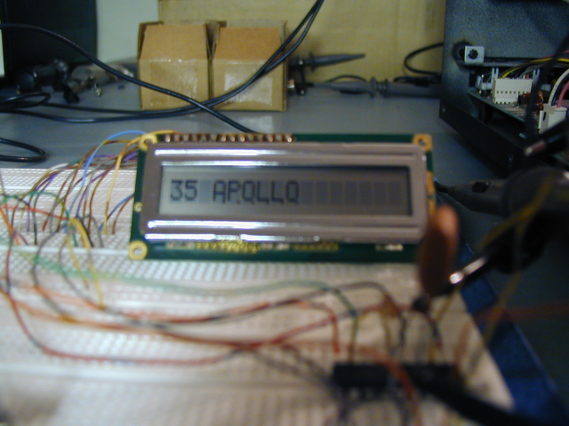
On my test unit, I used a small ribbon cable to grab the three logic signals, and clip leads for power and ground. I took some photos that show how the text looks on the M6R and on my 1x16 LCD. Most people would want to use a backlit display for a better appearance. I used what I had on hand. Any 44780-based 1x16 LCD should work fine with my code. Note that 2x16, 2x20, etc use different addressing and will not work without a code change. There are lots of color choices, and backlight options available. Keep in mind that the backlight current must be supplied by the M6/M6R, so I would suggest using one of the newer modules that has a 5V backlight with a current of less than 50 mA, or you could have issues with overloading the M6R power supply. The LCD and the PIC together, with no backlight, draw about 2.75 mA.
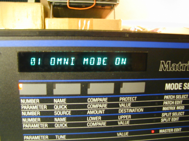
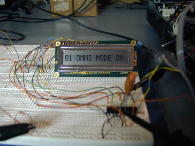
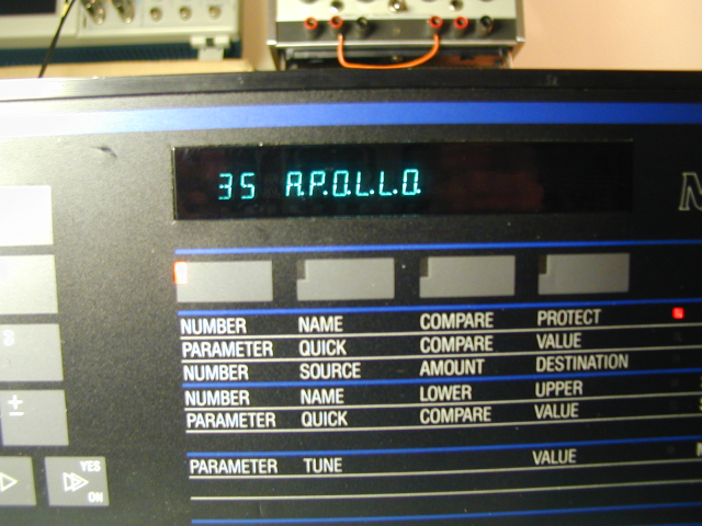
Here are some photos that show the M6R display and the LCD. The only challenge in the code was getting the LCD to display periods at the bottom of normal characters, as the M6R does, to show which voice is playing. The 44780 treats the period as a separate character, and allocates one of the 16 display positions to it. This would not have worked well here, so I had to figure out how to handle periods differently. The last photo shows the result (sorry that it's blurred).
Here is a schematic showing the PIC connections.
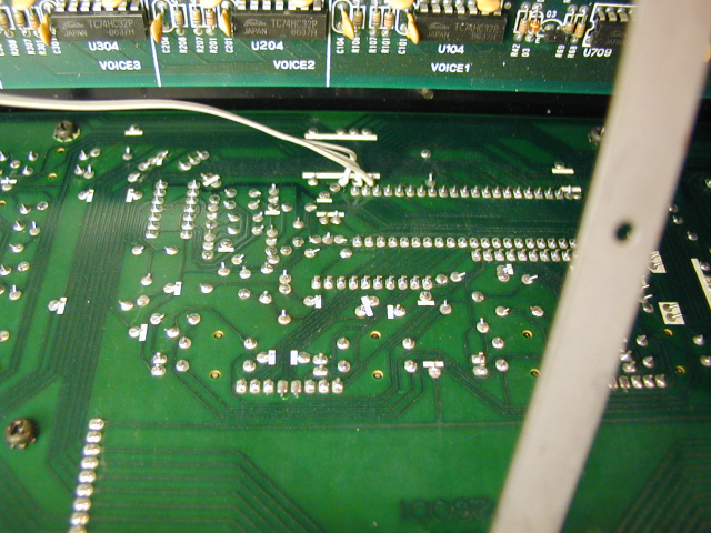
And here is a photo showing possible connection points on the rear of the M6R front panel pc bd for the three logic signals. (I will try to get a better photo)
I will supply PIC assembly code, or a hex file for free to anyone who is interested in it. If there is enough interest, I will make a small pc bd available that holds the PIC chip and plugs onto an LCD module. Fitting any LCD inside an M6 or M6R would require removing the VFD display. Also, many backlit displays are too deep to fit in the space available, although I think there are some that will fit. I do not plan to provide anything other than the code, schematic, and possibly (if there is enough interest) a small PC bd to hold the interface. It is a pretty simple circuit, and could easily be wired up by hand on a perf board.
DISCLAIMER: I take no responsibility whatsoever for the use and/or implementation thereof, or the misuse leading to damage to equipment, property, or life, caused by the above circuits.