Radio Shack/Moog MG-1 Info
Replacing the MM5823
The polyphonic section of the MG-1 uses a top-octave divider chip plus some MM5823 chips to divide by two and four. In my unit, two of the MM5823 chips were damaged and getting rather warm. The outputs were not toggling. I looked on the web for replacements and found only a $25 plug-in board. This seemed a little expensive, so I decided to make my own replacement. I used two SMT CD4520 dual counter chips and designed a small pc bd that can plug into a std DIP socket.
Here is a schematic of the circuit.
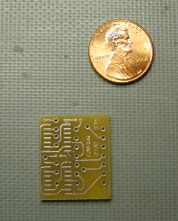
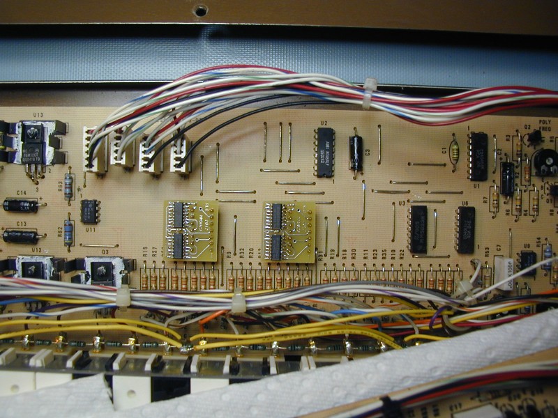
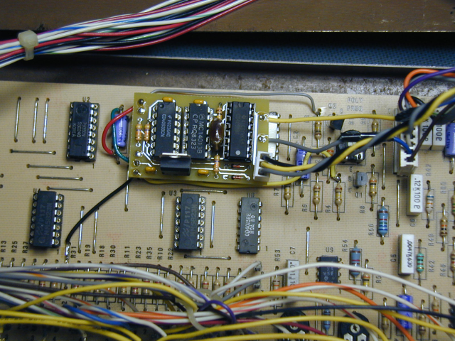
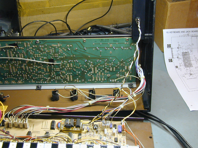
Here is a picture of the bare pc board, and here is how two of them look installed in my MG-1.
I have more of these boards, so please contact me if you need to replace an MM5823. The boards cost me about $2.50 each and the chips are about $0.50 at Digi-key. I installed machined-pin IC sockets in the board and then plugged the small boards into them, but solid core wire could also be used to solder the boards directly to the MG-1 PC board if desired.
Speeding up the MG-1 keyboard response
I have seen some posts mentioning the slower response of the MG-1 keyboard, and also found a post suggesting a mod to improve it. I decided to implement that change on my unit. The suggestion was to reduce the discharge time of the peak detector circuit used to generate the keyboard trigger signal. This circuit uses the polyphonic signal as its input. The resistor that discharges the cap is R47, located on the lower board. The standard value is 200K. I varied this resistor and measured the time from the end of the last positive pulse on the anode of CR1 to when the trigger signal shuts off:
200K -> 62 mSec (factory value)
67K -> 20.4 mSec
38K -> 11.6 mSec
33K -> 10 mSec
23.8K -> 7.2 mSec
These times depend on the exact value of capacitor C6, so they will vary a little from unit to unit. On my board, at 22K ohms or below, the circuit re-triggers constantly during the lowest note of the keyboard if the key is held down, so the circuit is no longer working correctly. I installed a 33K resistor for R47 and thought I was finished. But after some additional experimentation, I discovered that simply playing the lowest note on the keyboard is not actually the worst case for finding the minimum acceptable value for R47. It turns out that with a 33K installed, if I held several low keys together, such as the lowest key and the one next to it, I still got the false re-triggering. I increased R47 to 68K and the re-triggering went away. This still makes the response much faster than with the factory value, just not as fast as with the 33K installed. I tried a simple "before and after" test playing two notes alternately as fast as I could. With the 200K resistor, the MG-1 triggers at the start, but does not re-trigger as I keep playing. With the 68K installed, the MG-1 keeps triggering over and over, as it should.
Applying Modulation and Contour (Envelope) only to Oscillator 2
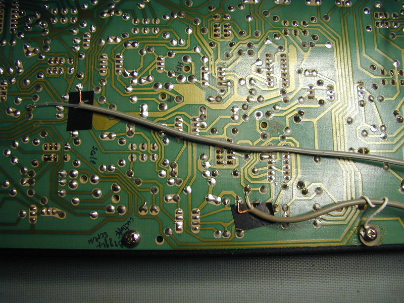
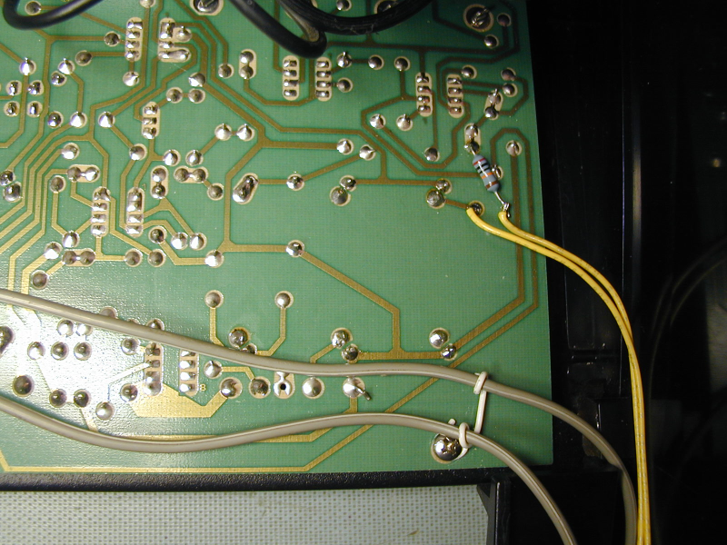
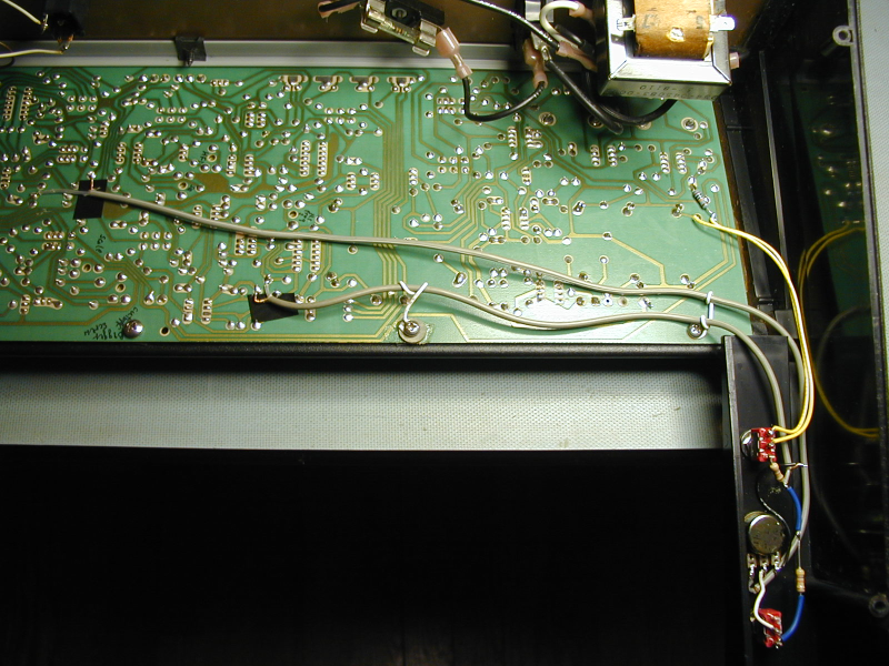
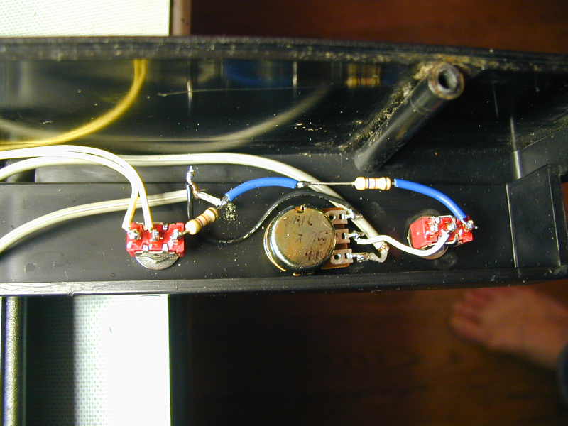
A friend was interested in modifying his MG-1 to optionally route the modulation only to oscillator 2, especially useful in sync mode. We found some information on how to do this on the web and applied it to his unit. This meant connecting the mod signal to U4-2 instead of to R70, which affects both oscillators. After he played with it for a bit, he noticed that this mod threw off the tracking of oscillator 2 when enabled. Hmmm. By connecting the modulation at this point, we were also changing the impedance, which changed the effect of the pitch voltage on osc 2. After examining the schematic, it seemed to me that applying the modulation at U5-6 instead might fix the problem. I tried it, and decided that it was working, so we changed his unit to use that connection instead. He also wanted a way to apply an adjustable amount of the contour voltage to only oscillator 2. This was applied at the same point (U5-6). Since this is a virtual ground, these extra currents do not interfere with each other or with normal tuning. Here is a schematic that shows how the connections were made. And below are some photos that show the same mods, applied to my MG-1: (I used shielded cable to run the signals over to the side panel. We found that this was necessary on the U5-6 signal to prevent audible noise pickup, so I decided to use it for the other signal as well. One of the shield grounds is used at the potentiometer. The other is only connected at the pcb end.)
Selectable Poly/Sub Osc 1/Sub Osc 2
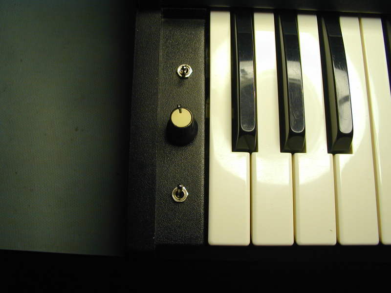
A friend was interested in adding a sub oscillator to his MG-1 in place of the polyphonic signal, using the poly slider as a level control. We came up with a simple mod. Afterward, I decided it would be nice to have the option to select either the poly signal, sub osc 1, or sub osc 2. I designed a small pcb with the needed circuitry, to make the mod easier. All of the required connection points are fairly close together. The only cut needed is for inserting the circuit in series with the poly signal as it goes from the lower board to the main board. Here is a schematic for the circuit board, and below are some photos showing the installation and the center-off toggle switch that selects which signal is routed to the poly fader. An unexpected benefit of being able to select osc 2 as the sub osc source is that it produces a 50% duty square wave at half the osc 2 frequency, which can be set to about the same as osc 1, for that "two square waves beating" sound.
New switch dust covers
After the messy foam has been removed from an MG-1, Rogue, or Opus3, the aluminum housings for the toggle switches will be visible through the front panel openings. Some equipment uses black circular pieces of a very thin fabric to hide their switches. I found that the black plastic cover of obsolete 5 1/4" floppy disks is a good material for making these. Cut circular pieces roughly 1" in diameter, and drill a hole in them just big enough for the switch actuator.