A low-cost MIDI interface for the Kawai SX-210 Synthesizer
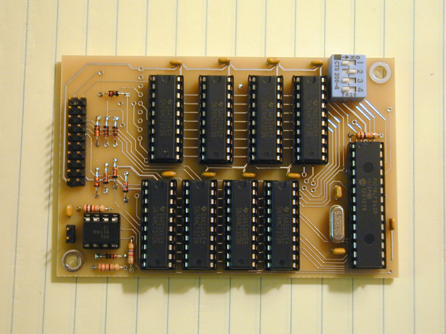
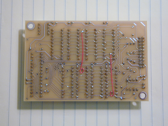
A friend recently asked me if I could design a simple MIDI interface for the Kawai SX-210. Because of the slightly unusual way that the keyboard is scanned, some other generic MIDI interfaces will not work in this synth. Most other synthesizers that use a matrix-wired keyboard latch the row (drive) signals and hold them for tens of uSecs or so before reading the columns to see which keys are down. The SX-210 simply drives the rows from a decoded CPU address with no latching, so the row pulses are much shorter, on the order of 900 nSec long. This makes the design of a MIDI interface a little trickier. I decided to take a brute force approach to keep the design simple. As I don't expect a lot of these will be made, the extra parts cost is not a big deal, and there is room inside the synth for the pcb area needed. My design uses eight octal latches, which are loaded with the correct data for each row of the keyboard, based on MIDI note on/ off commands. The output enable of each latch is driven by one of the row enables from the synth. You can find a link to the schematic further down this page. I used through-hole components to make it easier for people to build. This interface only supports note on/off and MIDI reset. The bottom key is mapped to MIDI note 36 (C). A switch is provided for MIDI channel selection. I have personally installed this in two SX-210's, and have also shipped seven pcb's, with no problems reported. Here is how it looks. The MIDI cable attaches to the two-pin header. The other connector is used for the keyboard signals, +5V, and ground. These connections would be made with a ribbon cable with bare wires on one end which are tack-soldered onto the bottom of the SX-210 pc bd. Two jumper wires need to be added to the bottom of the MIDI board to complete the circuit. (At one point there were three, but I managed to route one of them) This board is pretty full and the size is fixed by ExpressPCB at 3.8" x 2.5".
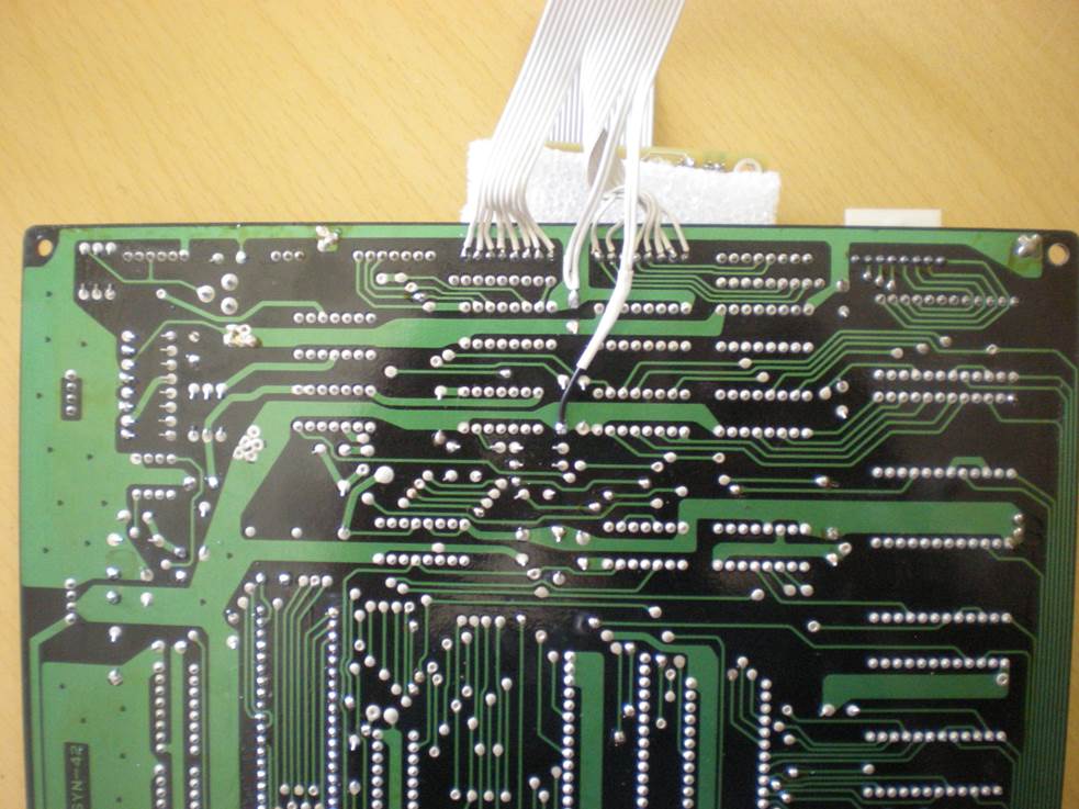
Here is how the ribbon cable wires should look when attached neatly to the bottom of the SX-210 pcb: (Notice that both wires are used for +5 and ground to get a low-resistance connection)
Here is a copy of the schematic. The PIC interprets MIDI commands to press and release keys. Local keys can be played at the same time.
Please note: This interface does not allow saving, changing, editing, or restoring patches, or doing anything other than playing notes over MIDI. It should only be assembled and installed by someone with an adequate understanding of electronics. If it is assembled or installed incorrectly, damage to the SX-210 circuitry could result. I will not be responsible for any damage to any instrument caused by either proper or improper use of the design presented here.
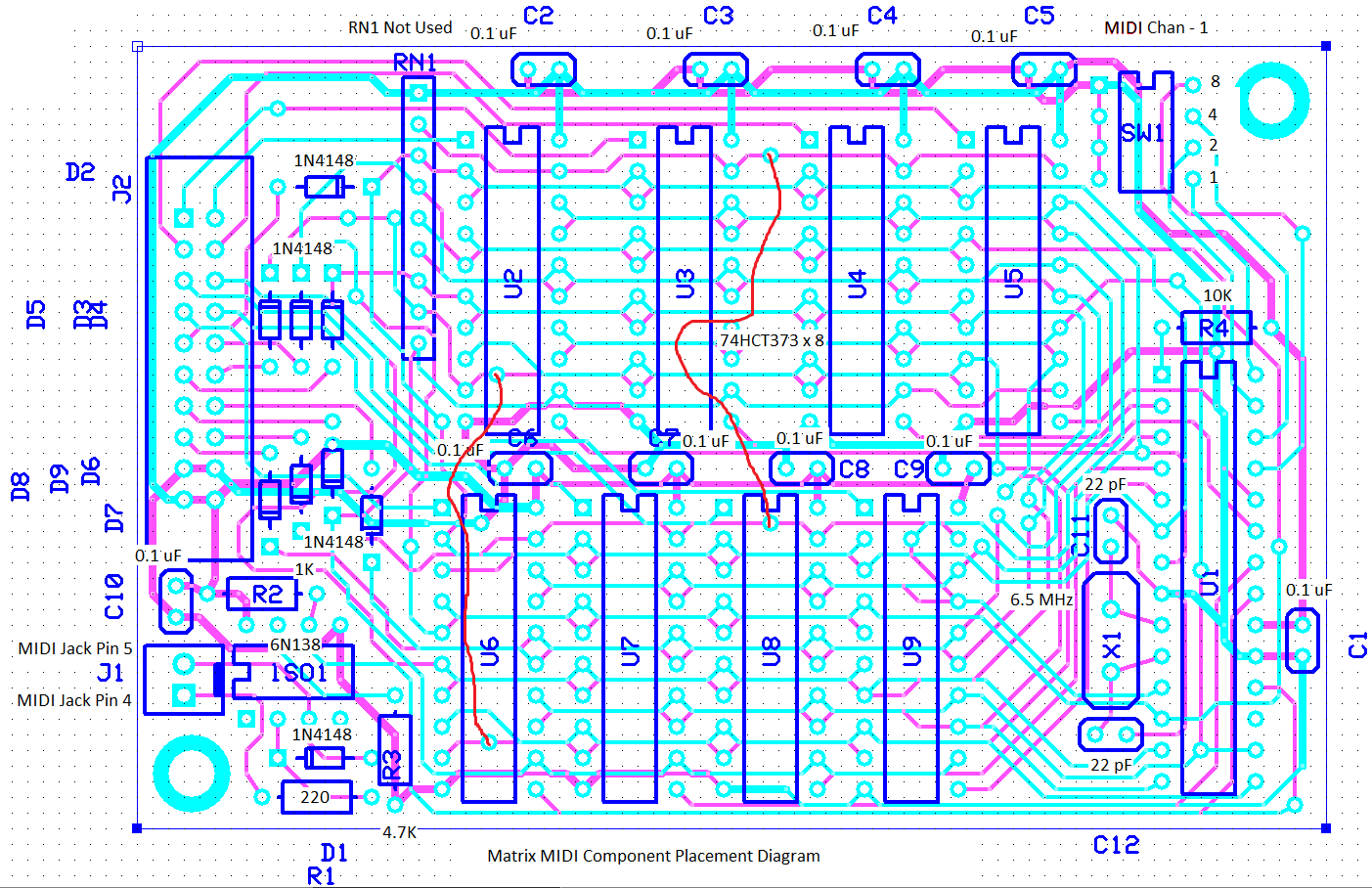
I am offering blank pc bds for $30 each (plus S&H) and programmed PIC chips for $7 each. Please contact me if you are interested. I will not offer assembled boards. You will need to order the other parts yourself and put it together. Do not attempt this unless you have decent soldering skills. This is not a good project for learning how to solder. All of the parts are standard and can be purchased at Digi-Key or Mouser. Here is a parts list for the interface. Here is a component placement diagram.
There is room on the inside of the back panel to attach the circuit board. I would suggest using stick-on nylon standoffs to support it, but other mounting techniques should also be fine. One I have used is to cut a flat sheet of aluminum to be about the same size as the pc bd. Mount threaded standoffs to it that line up with the pcb holes. Adhere it to the inside of the back panel with permanent double-stick foam, and then mount the MIDI pcb on the standoffs with screws and lockwashers.
Keep the keyboard ribbon cable as short as you can. I have not seen any problems, but did not try using a really long cable.