dk Synergy Digital Additive 80's Polysynth
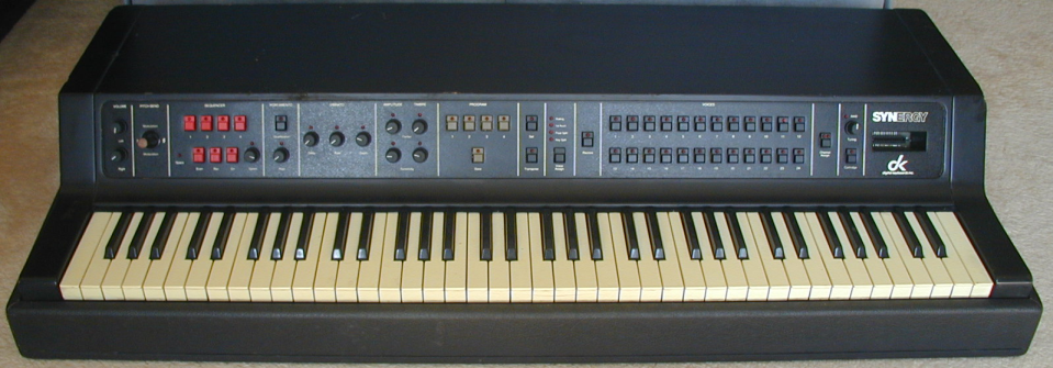
I was recently contacted about repairing three dk Synergy synths. Two were the first version, and one had the VRAM and SIA daughter boards installed, making it a II+ model. The Synergy is rather different from other synths I have worked on, so there was a lot to learn.
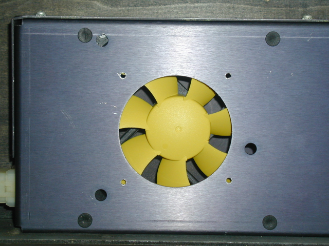
One of the lesser Synergy's had been powered up recently by its owner and found to work, but the cartridge sounds were incorrect. I powered it up, and was struck by how incredibly noisy the power supply fan was. The voltages all looked OK, and the internal presets seemed to be working. Three of the front panel switches were inoperative. (One red, one gray, and one black) Luckily the switches for the Prophet 5 work fine as replacements and are available from Syntaur in black and gray. I was able to get red ones on ebay from a seller in Israel. The cartridge port is connected to the processor board with a ribbon cable. This cable is plugged into a socket at the processor end, but the other end has an IDC connector with pins that solder into the pc board that holds the cartridge edge connector. The cartridge ribbon cable has a shield around it which does not bend easily. This shield tends to prevent the cable from bending properly at the cartridge end, and can cause it to pull apart the IDC connector, breaking some of the connections. This was the cause of the flaky cartridge port. I replaced the IDC connector with a new one, and cut back the shield to leave about 1" of the ribbon cable free to bend at the cartridge end. If you do this, be careful not to cut the ribbon cable when you are cutting the shield back. Chris Hewitt, an experienced synthesizer tech in CA who had recently repaired a Synergy, suggested replacing the noisy AC-powered fan with a much quieter 12V DC one. This required adding a 7812 inside the power supply to regulate the approximately +20V down to 12V for the fan. I installed this fan (Silenx EFX-14-12 Effizio 48CFM) in all three Synergy's:
With the first unit up and running, I decided to take a look at the II+ model. The SIA board had come unplugged from the processor board and was totally disconnected. I didn't care for the way this board was connected, so I cut off the wire-wrap socket pins enough to solder two strips of round gold headers to them:
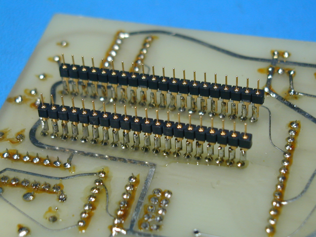
Then I removed the IC socket for the CPU from the processor board and replaced it with a machined-pin socket to mate with the round header pins.
Note: Component height underneath the Synergy keybed is limited to about 1.13" max according to my measurements. The daughter boards just barely fit into this space, and it seems washers were added under the feet of the keybed to raise it up a little so nothing would hit. Any changes to connectors, or even capacitor replacement must be done carefully to avoid increasing the height of the daughter boards.
The new connectors will provide a more reliable connection from the CPU to the processor board. I later installed the same headers and IC sockets for the VRAM board, although the original connectors were still in their IC sockets. The pins of the headers used on the VRAM board are all facing the same way, and are thinner than the wire-wrap pins used on the SIA board, although still much thicker than the pins of an IC. The pins of the 40-pin wire-wrap IC socket are square, and are at random angles of rotation. So they didn't work well as something to plug into a stamped IC socket. The headers used on the VRAM board are better, but not as good IMO as using round headers and IC sockets with round holes to match. Of course Mulogix didn't want their upgrade to require replacing IC sockets on the processor board. Once I got the SIA board connected properly, the II+ Synergy started working. MIDI, however, was totally dead, and I could see that the UART was never sending anything, even though data was being written to it and the clock signal looked OK. I ordered and installed a replacement COM8017 chip, which fixed both MIDI transmit and receive. Luckily, the FIFO chip was OK, as those are also difficult to obtain. I ran the memory tests, comm loopback test, MIDI test, and front panel built-in tests and everything passed. Next I tried the four cartridges that the owner had supplied and they all failed the cartridge test. This test computes a single CRC value from all cartridge data bytes and checks it. If all bytes read correctly, the result will be 0000. Any other result indicates that the data is wrong, or is not being read reliably. Although it's possible that the EPROM(s) in a cartridge could be corrupted from "bit rot", in my experience poor connections are much more common than bit rot. I cleaned the contacts on the edge connector in the cartridge port and the edge fingers on all four cartridges, and now they all passed.
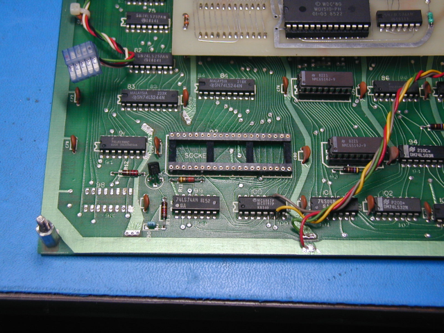
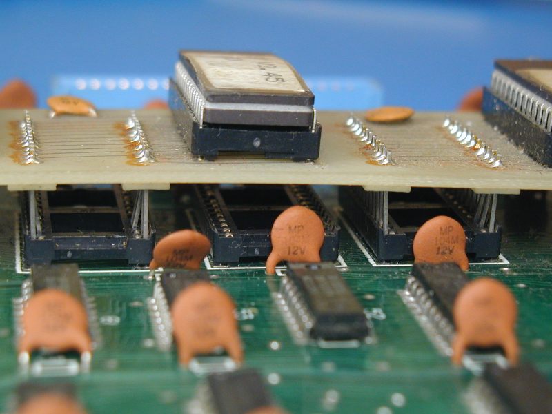
The third Synergy was completely dead, although the power supply voltages were correct. I determined that the CPU clock was not running. This is derived from the 32.768 MHz can oscillator on the oscillator circuit board, which had failed. Replacing this brought the third unit back to life. Interestingly, this unit had three 2764's for the code firmware, mounted on a small daughter board. I am not sure why this was done, as the sockets for 2732's had been installed on the processor board, and using them instead of the daughter board with its marginal connector would have been better, IMO. This photo shows how the daughter board pins were inserted into the IC sockets on the processor board. You can see that some inserted themselves into the wrong part of the IC socket:
Now that I had all three units more or less working, I started working on capturing schematics for new II+ daughter boards, so I could upgrade my two units to the II+ configuration:
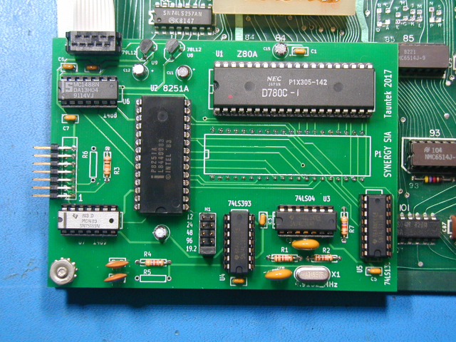
For the SIA board, I moved the CPU to its own IC socket, to allow using the round gold headers. Luckily, the original SIA board had lots of empty space on it, so I was able to do this, and still fit the same circuit onto a slightly smaller pc board. Luckily the 8251A UART chips are still easy to obtain and inexpensive. I changed the pinout of the ribbon cable connector for the serial port so that the first 9 wires could connect directly to an IDC DB-9 connector mounted on the Synergy back panel. I used a ribbon cable for the power supply connections as well, as it is easier to make up, and used two wires for each signal to get lower resistance. Here is the new SIA pc board:
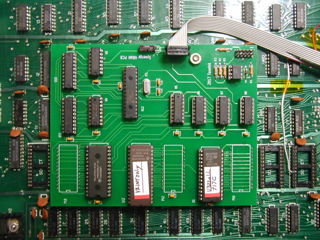
Several changes seemed obvious for the new VRAM board. The original used three EPROMs for the firmware. These could be combined into a single larger chip. The four SRAMs used to implement the VRAM buffer could also be combined into a single chip. The original design used a COM8017 UART for the MIDI interface, and a FIFO chip to buffer the MIDI receive data. (I think the FIFO was used because the UART does not generate an interrupt to the CPU, so they were concerned about losing data in-between polls) Both the FIFO and the UART are obsolete parts, so I decided to use a PIC microcontroller as both the UART and the FIFO. This change plus combining the memory chips made it possible to shrink the pc board significantly. Since the board no longer makes a connection to the socket for IC76, I added a wire to the ribbon cable to feed the chip select signal to the VRAM board. Interestingly, although the data and address buses are common to all of the memory chips on the VRAM board, they are not connected on that board. Each chip makes its own connections to the processor board for these signals. I would have thought connecting them together on the VRAM board would offer some redundancy, so even if a header pin connection was lost on one address or data line of one chip, that signal would still be connected by the trace on the VRAM board. Also, the power pins of the memory chips do not connect to the power pins of the other chips on the VRAM board. My board matches the original in both of these respects. Here is the new VRAM pc board:
Cartridges built-in
The Synergy uses the same memory space for either the 8K internal presets EPROM, or the 8K of cartridge EPROM. Only one is active at a time. This suggested to me that the format of the data must be the same in both. In the new VRAM design, I used a 2Mbit chip for the internal presets EPROM. This is 256K bytes, or enough space for 32 8K cartridge images. The PIC which emulates the UART and FIFO chip controls which bank/cartridge is selected. I currently have 22 cartridge images plus the V2 internal presets in this chip. I modified the Synergy OS to send a special command to the PIC chip to select the bank. To change banks, press Restore, then Program 4, then voice sw 1-23. The Synergy will restart after the bank is changed. If voice sw 24 is pressed, the comm link test code will execute. I have only done a small amount of testing of the preset banking feature, but so far it seems to be working. With this scheme, it should also be possible to plug in a real cartridge and press the cartridge switch to enable it, as before.
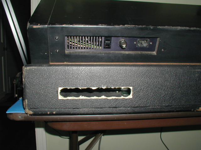
To make a hole for the new jacks, I removed a 6 and 5/8" by 1" strip of Tolex, then drilled a number of 1" diameter holes and used a chisel to remove the bits in-between them. Here is how it looked:
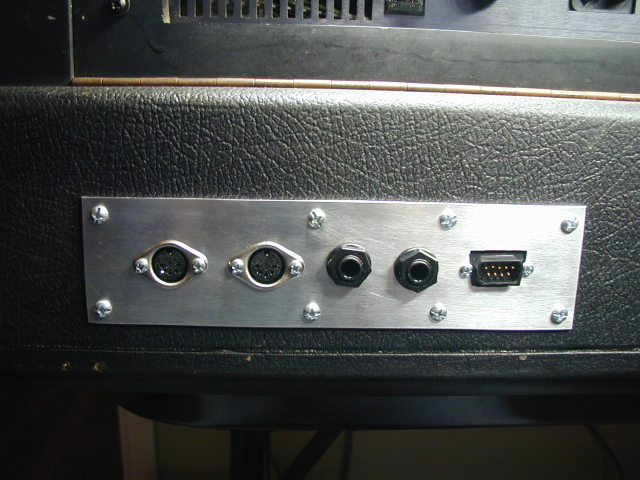
I cut a rectangular plate of 1/16" aluminum 7 and 3/4" by 2". A 5/8" chassis punch makes the correct hole for MIDI jacks. Cutting the hole for the DB-9 was done with a "nibbler" tool. The new jacks are MIDI Out, MIDI In, SEQ out, REC out, and serial port:
Tests run so far with the new boards
I have run the processor memory tests, which also tests VRAM, comm link test, comm loopback test, and the MIDI data path test. I also connected a Kaypro II and downloaded several cartridge files using SYNHCS. So far everything looks good.
Board sets available
I can supply bare pc boards if anyone wants to tackle upgrading their Synergy to a II+. I have shipped ~30 sets so far and am currently out of boards, but will soon be ordering another set of 16 boards. I can also supply a programmed PIC chip for the UART/FIFO emulation, schematics, and images for the two EPROMs. You will need to program your own EPROMs. I can also supply the PIC chip hex file if you can program your own. Boards are $50 for a set of two, plus postage. Programmed PIC chips are $10 each. I also have a small pcb which holds two reed relays, used to isolate the SEQ and REC outputs as the Mulogix II+ upgrade did. That board is $5. I will not be selling populated boards, so please don't ask me. Performing the upgrade involves buying and soldering components, cutting several pcb traces and installing jumpers on the processor board, removing IC sockets and installing different ones in four places on the processor board, wiring up ribbon cables, etc. You should not attempt it unless you have a lot of experience with these kinds of tasks, as you could easily damage your Synergy. Note: The ribbon cable connector pinouts on my boards do not match the original Mulogix daughter boards, so these boards are not interchangeable with the old ones, and were not intended to be.
Here is the schematic for the new SIA daughter board. And here is the schematic for the new VRAM daughter board.
Here is an archive containing the source code and generated hex file for the PIC code I wrote to emulate the obsolete MIDI serial chips. Note: This code is the property of Bob Grieb and is not to be used for commercial purposes. If you would like to use it in a commercial product, contact me.
Here is a document showing the MIDI commands supported by V3.22 of the Synergy code.
Please note: The pc boards offered here should only be installed by someone with an adequate understanding of electronics and the tasks involved. If they are installed incorrectly, damage to the synthesizer circuitry will result. I will not be responsible for any damage to any instrument caused by either proper or improper use of the design presented here.
Other misc. improvements that Synergy owners may want to consider are: Replacing the tantalum caps with new aluminum electrolytic equivalents. If a tantalum cap was used right at the output of a voltage regulator, I replaced it with a new tantalum. Otherwise I used an aluminum electrolytic cap. This was preventive maintenance. I can't say that any of the tantalums I replaced were actually bad, but they were 35 years old, and do tend to fail (shorted!). Of course you need to be careful to install the new caps with the correct polarity, and if you don't have a lot of experience soldering, better to just leave them alone. I also replaced six (RCA) CD4051B chips located on the front panel pc boards. There are two of these chips on each of the three boards. You only need to remove one of the boards to replace them and they are already in sockets. Several of these chips had already failed and were causing switches and pots to be read incorrectly. These chips often fail in other synths, so replacing them seemed prudent. There is a lithium battery mounted in the right front corner of the processor board. I had never seen a battery like this one, so at first I thought it was a piezo beeper. The battery, which preserves the contents of the two CMOS RAM chips when power is off, was completely dead on two of the Synergy's. I bought CR-2450 replacements with solder tabs.
Other misc. parts which needed replacing: One of the 74C151 chips on the keybed assembly was bad on one Synergy. This kept some of the keys from working. This should be a 74C part, not 74LS or 74HC. The left channel was very "tinny" sounding on one unit. The right channel was fine. This ended up being an open primary winding on the right channel output coupling transformer, which is located on the DAC board. The Hammond 109N 10K:600 ohm transformer seems to be an acceptable substitute for the original ADC part. Luckily, it has the same footprint, so installation is easy.
Did you want ALL of the keys to work?
Upon re-assembling one of the units, I discovered that a number of the keys did not work properly. When a key is pressed, a small spring breaks contact with the lower bus bar and makes contact with upper one a short time later. Both of these contacts need to be working in order for the velocity sensing to work. I had already removed the bus bars and cleaned them, but cleaning the springs is a lot trickier, as you don't want put a kink in them or bend them. Close examination of the springs for the keys that didn't work reliably showed that they were not making good contact to the lower bus bar when the key was released. I was thinking that what was needed was some way of adjusting the position of the bus bars so that the springs would be pressed against both of them equally at the two ends of their travel. As it turns out, there is an adjustment for this. The contact pc board and black plastic spring guides are held by screws to a rectangular metal piece that runs the full width of the keybed. At several points along its length, this metal piece is fastened with two screws in slots, which can move up or down when loosened. This moves the bus bars up or down relative to the back end of the keys, and can be used to center the contact springs in the bus bars. It's pretty much impossible to make this adjustment with the keybed mounted in the Synergy. Luckily, the keybed works fine with a ribbon cable that is 55" long. Using this cable, you can put the keybed on a workbench, and place the Synergy on the floor or a different workbench. One of the contact springs broke off while I was testing the keybed. Luckily, they are a little longer than needed, so I removed the broken part from the pc board eyelet, (from the bottom, as it won't fit through the hole) then I cleaned about 1/8" of what used to be the free end of the spring with some fine sandpaper, so that it would take solder, then soldered that end to the pc board, and fed the spring (carefully to avoid kinking it) through the black plastic guide and into the key actuator nylon piece. I had cleaned the spring with a gum eraser before re-installing it. It works fine.