AKAI ASQ10 MIDI Sequencer Front Panel Repair
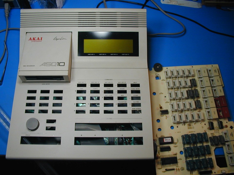
I was recently helping someone troubleshoot an AKAI ASQ10 with unresponsive front panel switches. (He had bought it in this condition) All DIP IC's on the front panel had already been replaced. Also, the MCU now had a 6.0 MHz ceramic resonator installed, and the EPROM had been replaced with one labeled "MPC60". We knew that the MCU resonator was supposed to be 12 MHz, not 6. I did not have the correct resonator, so we installed a 12.0 MHz crystal and two 22 pF capacitors. Now the MCU oscillator was running at the correct frequency. We also had a working ASQ10, so we dumped the front panel code EPROM from that one and reprogrammed our EPROM with that code instead. Still no switch response, and we could see that several outputs from the MCU were just floating. Hmmm. We thought possibly the MCU chip was damaged, but another possibility was that the code was not running and was not configuring these pins to be outputs. Checking the chip select to the EPROM revealed that it was also floating, and could be pulled to 5V with a 10K resistor. Next we compared the part number of the D78C11G MCU to the working ASQ10 and found that it was different. It seems someone had replaced the MCU and perhaps did not realize that it had AKAI code inside. We were ready to give up on the repair, since it seemed that we would need to find the correct MCU from an ASQ10. Here is a photo of the board with the wrong D78C11G chip installed:
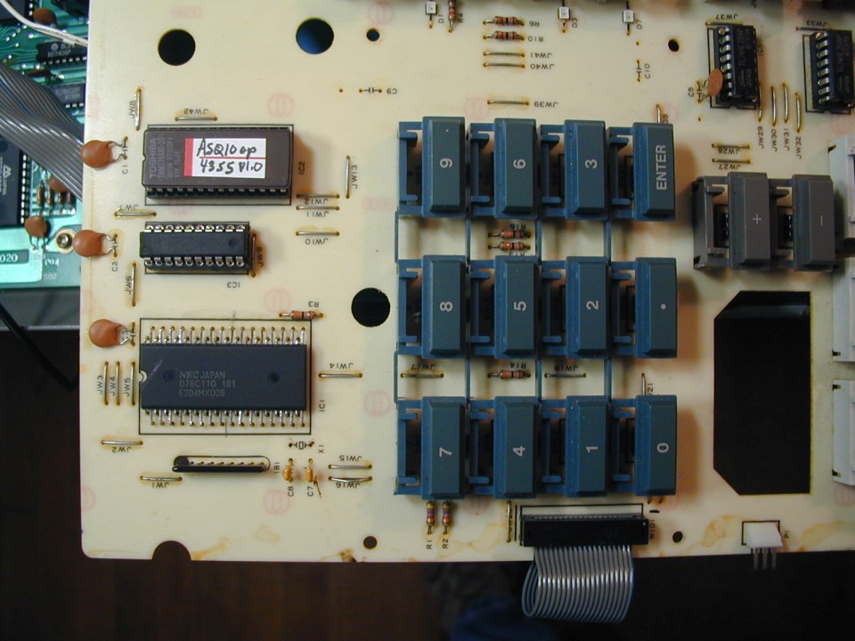
As you can see, the full part number is D78C11G 181, which is not the correct part for an ASQ10. Also, the date code on this part is 1992, which is too late for an ASQ10.
Several AKAI products from the 80's used the 78C11 MCU with code inside. But in some cases, the internal (boot) code did almost nothing except write to a few registers and then jump to address 4000H, which is the start of the external EPROM code. So really, all of the code that was specific to that product was in the EPROM. This made it possible for them to use the same exact 78C11 part in several products. So possibly, the ASQ10 front panel MCU was the same, with just enough internal code to jump to the external EPROM.
I looked at the EPROM code a little, and it looked like the instructions to configure the I/O ports were there. It seemed that if we could just get the CPU to jump to that code, it might work. But how? I know that some other MCU's with internal ROM also have a way to force the chip to execute from an external EPROM instead. Was it possible that the D78C11G had such a mode? The D7810 is a ROM-less version of the same MCU. There are two "Mode" pins on both the 7811 and 7810 which affect the external memory addressing. The data sheet says to always tie Mode 1 high and Mode 0 low for the 7811. The other three combinations are only used with the 7810 to select the size of the external address space. If both pins are tied high on a 7810, the external EPROM space extends from address 0 to 64K. (In a 7811, the external EPROM starts at address 4000h) I wondered what would happen if I tied both pins high on a 7811 chip, instead of doing what the data sheet said to do. Would it behave like a ROM-less 7810, and boot from the external EPROM? Turns out, it does. (Mode 0 must be tied to 5V through a 10K resistor, as it becomes an output after booting) The actual code in the ASQ10 front panel EPROM is just over 1K, so address line A12 is always low. In the new mode, I figured the 7811 would drive A12 high when executing from address 4000h, which would not work correctly, since the code is at the beginning of the EPROM. Since the actual code space used is only ~1K, A12 is always low, so I simply tied A12 on the EPROM to ground. Since the entire address space would now be mapped to the external chip select, the EPROM contents would appear at 0x0000, 0x1000, 0x2000, 0x3000, 0x4000, etc. (We only need 0x0000 and 0x4000) At the start of the EPROM code, there is a relative branch, so the code at the branch address would still be executed at around address 0x0000. Eventually, either a call or a jump to an absolute address around 0x4000 is executed, and after that, everything is executed where it would normally be. With the two changes, the MCU started scanning the front panel switches and sending serial data to the main CPU when a button was pressed. Cool!
So the upshot is that I was able to use a D7811G chip with the wrong ROM boot code in it, and get it to work. I am not ready to say that this would work for other AKAI synths that used the D78C11G but I think it might be possible. One complication is that interrupt vectors would normally be in the internal ROM. Luckily the ASQ10 front panel MCU does not use interrupts. In the AX-80, the interrupt vectors in the ROM just point to similar locations in the EPROM. Another approach that might work would be to use an EPROM that is twice the size needed for the external code, and place the AKAI bootloader code at the bottom, with the normal EPROM code at offset 4000H in the EPROM. Then tie both mode pins high so that all memory is mapped to the external EPROM. This would require obtaining an image of the bootloader internal ROM, of course. I think the AKAI D78C11G 144 MCU may have this code in it.