MIDI Interface for Early Revision Elka Synthex Synthesizers
Here are some code EPROM images for two versions of the firmware suitable for use in the Rev 1 unit pictured. These had four 2516 EPROMs, with the CPU data and address lines connected to the chips in an unusual way, thereby scrambling the data if you read it out using normal connections. So the designers would have had to pass their code image through some sort of software or hardware adapter that would scramble the address and data lines to the chips for programming. Unfortunately, I was not able to read one of the EPROMs from the version 0.4 code. The P1.4 EPROM seems to have stopped working, so I have not included any data from it. The last 4 digits of the file name are the 16-bit checksum of the file data.
Here is an archive containing two different versions of the Synthex Rev 1 firmware. The EPROM labels indicated V.4 and .5 These are images of the data as a normal EPROM programmer would read them, not as the Synthex 6502 would see the data. To make any sense of the data in these EPROMs, you would need to un-scramble it first. This code is from the early Synthex which had four 2516's, and would not work in the later units, which used 2532's.
New MIDI Interface for early Revision Synthexes
As many people know, Elka never offered a MIDI interface for the earliest version of the Synthex. These are the units which used four 2516 EPROMs. Because the design is different, the MIDI code written for later units would not run on them, even if there were enough room in the EPROMs. My first project was making a MIDI interface that would hook into the keyboard connections and allow Note On/Off control. This was done in March of 2018. More recently, I became interested in trying to understand the differences between Rev1 and later units with the hopes that a "real" MIDI interface could be made. I don't own a Synthex, but someone sent me the CPU and chorus boards from a Rev 1 Synthex for repair and reverse-engineering. I have now generated schematics for these two boards, which you can find below. Mapping out the decoding and cable wiring on the Rev1 CPU board made it possible to create a version of the MIDI board and the MIDI firmware that works with the Rev1 Synthex. The firmware is pretty much the same firmware that I offer for the Rev2 and 3 units, with some small changes to allow it to work with the Rev1 Synthex hardware. This firmware supports parameter changes using received MIDI CC's, and saving and restoring of patches using sysex. In addition, since it is based on the Rev2 firmware, it has increased sequencer note capacity and non-volatile storage of sequences. (Note: CC's are not transmitted by the Synthex) A new EPROM pcb was designed to simplify the MIDI connections and increase the code space as needed for the MIDI firmware. So the installation requires two new pcb's to be installed. Also, two 1Kx4 CMOS EPROMs need to be installed in the two unused locations on the CPU board. No traces are cut and no jumper wires are added to the CPU board for this installation. It is, however, necessary to install the two new SRAM chips (in sockets) at the unused locations. Also, to get reliable connections to the new EPROM board, you will need to replace the original IC socket used for the 6502 chip with a machined-pin socket.
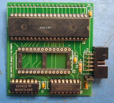
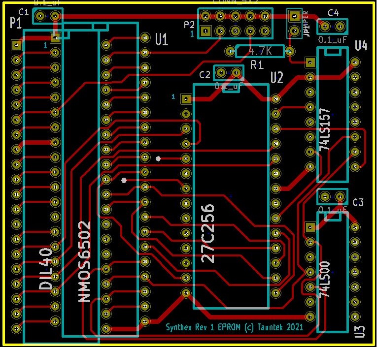
Here is the new EPROM board:
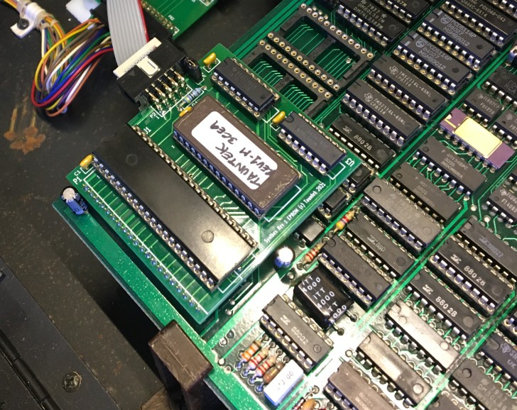
Here is an installed EPROM board. You can also see two new Philips CMOS SRAM chips on the CPU board.
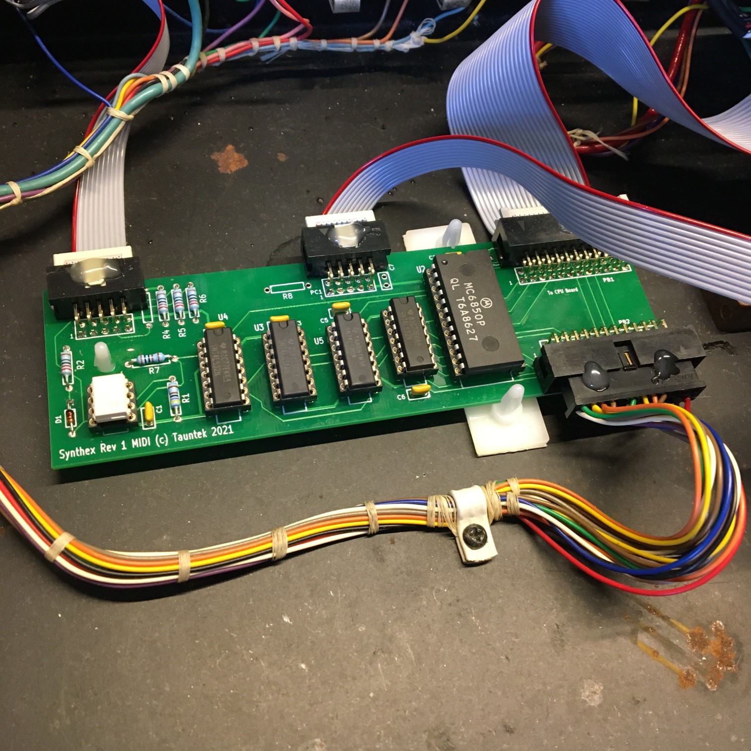
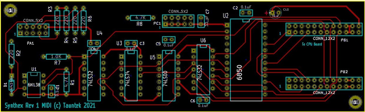
Here is the new MIDI pcb, blank, and populated:
![]()
And here is a photo (courtesy of Matt Padden of Matt's Keyboard Repair) of the MIDI board installed:
Here are the schematics that I created for the Rev1 CPU and chorus pc boards.
Here are the installation instructions for the new MIDI boards.
Here is the parts list for the EPROM pcb, and here is the parts placement diagram.
Here is the parts list for the MIDI pcb, and here is the parts placement diagram. Here is a drawing that shows how to wire up the MIDI jacks.
I am only offering blank pc boards, and the firmware EPROM binary image. The cost for the two pc boards plus the royalty for the new firmware is $100 . This does not include postage. You would need to order, or have someone else order the other parts needed and assemble the boards, and also make up the ribbon cables, before they are ready to install. I will NOT be offering assembled boards or cables. This is not a good project for learning how to solder. Building the boards and installing them must be done very very carefully, or damage to the Synthex will result. Only someone with solid electronics skills should undertake building and installing this interface.
Note: The "Rev 1" MIDI interface can only be installed in Synthexes that have four EPROMs on the CPU pcb. If your Synthex has only three EPROMs, this kit is not for you.
Adding four additional LEDs to Rev1 Voice Boards
Rev 2 and 3 Synthexes have two LEDs per voice board, to show when each voice is active. The Rev 1 board has just one LED, which lights if either voice is active. It is possible to modify a Rev 1 voice board to support separate LEDs for each voice. Here is some information that explains how to do it.
Please note: The information provided here is not guaranteed to be accurate. I will not be responsible for any damage to synthesizer circuitry caused by its use.