Some information related to Four Garfield Electronics Products
Dr Click 2:
I was recently helping a friend troubleshoot a Dr Click 2 sync generator which was no longer accepting MIDI input. We noticed that the Z80 chip does not have a RAM chip connected to it. This seemed odd, so we decided to dump the EPROM and have a look at the code. Here is a binary image of the 2716 used for the Z80 code, and here is a text file showing the source code. As you can see, the code was written carefully to avoid using any RAM. No pushes, pops, or subroutine calls. It's very simple code, so it wasn't hard to avoid using RAM, it's just a little unusual to see a Z80 with no RAM.
MiniDoc:
We were also recently working on a Garfield MiniDoc that needed repair. Without a schematic it was not an easy repair, and we gave up. It seemed that having a schematic would also be helpful to other people trying to fix these orphans, so I decided to create one. Here is a schematic of the pc board for the MiniDoc. Front panel connections are also indicated. I did not include the 5V regulator or its filter capacitor. This schematic was drawn using an ohmmeter and lots of notes, so it may contain errors, but should be a lot better than nothing. If you find something that seems wrong, let me know and I will fix it. The 96 PPS feeding to both mux inputs of the 4053 is not a mistake, but reflects cuts and jumpers on the unit. Here is a scanned copy of the user manual for the MiniDoc, courtesy of Tom Bugs.
Drum Doctor:
Someone recently asked me to repair a Garfield Drum Doctor. This is a six-channel dynamic drum trigger. Each channel has a Mic/Line input, trigger and dynamics outputs, and a separate VCA which is controlled by the level of the Mic/Line input signal. In addition, there is a Z80 CPU which monitors the trigger and level signals from all six channels and sends out MIDI messages when they are triggered. Some parameters of the MIDI messages are controlled by a set of 8 DIP switches for each analog channel. The CPU also measures the amplitude of the triggered channel dynamics signal and sends a velocity value based on it. I was not able to find any documentation on the web about this unit, so I decided to create some. Here is an archive which contains schematics for the analog channel and the CPU section. It also contains a binary image of the Z80 firmware EPROM and a disassembly of the code with some comments added. Lastly, there is some information on the MIDI messages associated with each channel and how to configure them. This information is not guaranteed to be accurate and may contain errors.
Dr Click:
Since I had so much fun drawing out the schematic for the MiniDoc, I decided to create one for the original Dr Click. I had never seen one of these and had no idea how much circuitry it contained. Someone sent me theirs to work on and learn about. When I first opened it up, I immediately decided to give up on capturing the schematic. Too much work. But then as I started trying to repair it, I realized how hard it is to work on these units without any schematic. It's a lot different from an analog synthesizer, where you sort of know the rough layout of things after working on a few. So anyway, I ended up capturing the oscillator/metronome board, since it had issues (bad crystal, CD4070, and CD4013), then ended up doing the front panel pc board and what I am calling the 48/96 output pc board as well. I did not draw out the FSK decoder or the memory board originally, but just recently I was repairing another Dr Click, and the rhythm generators stopped working during testing. I discovered that the 48X clock which drives them comes from the FSK board, so I drew out the remaining two schematics and added them to the archive. Hopefully my drawings will be a lot better than nothing and will make some repairs a lot easier. I found six bad 4000-series chips. Four of them were RCA 4013's with date code 1982. I also dumped the two 2716's that contain the divider ratios for the different thumbwheel metronome rate settings. I have put pdf's of my schems, the two EPROM binaries, and a copy of the Dr Click User manual in an archive here. My schematics may contain errors, since they were created with an ohmmeter and a lot of patience. (I think some of the notes I added about the frequency of clock signals at particular spots are incorrect) The front panel board was really trying, as the traces go all over the place, and run under chips on the top side, then you have to figure out which of the 3 traces that comes out the other side is that one. Or does it connect to a pin of that IC underneath it? By the way, my schematics of the 48/96 pc bd contain circuitry that seems to be generating 384X and 64X outputs, which the manual does not mention. These are accessed by pushing cables only part-way into the 24 and 12X output jacks. Maybe these were added in later versions? The second Dr Click that I worked on had 11 bad 4000-series CMOS chips, located on five different pc boards. Ouch!
Note: My Dr Click schematics were made from a unit containing the memory function. These have two pushbuttons and an LED mounted on the front edge. Units that do not have this feature contain two fewer pc boards inside, and the rear panel jacks connect directly to the front panel pc board, instead of passing through what I call the 48/96 output board. Probably the front panel pc board is a little different on these (earlier?) units. Also, one that I saw recently did not have any silkscreen to identify the IC's. The chips are numbered in relation to their placement on the pc bd. Looking from the top side of the board, left rear is U1, then the chip in front of it is U2, etc. When you reach the front edge of the bd, shift right and go back to the rear for the next chip. Once they are matched up to the schematic, you could write the numbers on the pcb with a Sharpie.
A note about the front-panel switches used on the Dr Click:
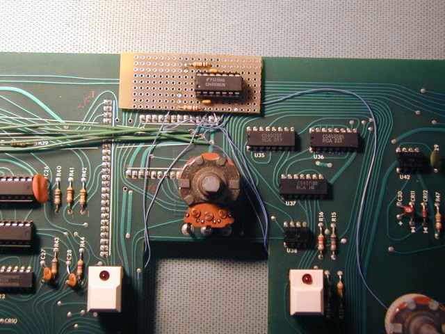
These particular switches with LEDs are no longer readily available. (The Prophet 5 used them too) They do show up on ebay from time to time. There are many in the Dr Click and a number of them in the unit I am working on bounce rather badly. If you look at the front panel schematic, you can see that the switch circuit for the rhythm selection is different from the circuit for the other switches. It is much less tolerant of switch bounce, which is OK for the individual function switches. I simply could not get the stock rhythm select circuit to work reliably, so I added a little circuit to delay the strobes to the two switch registers roughly 10-15 mSec. This gives the switches a chance to stabilize before registering their states, and should have been part of the original design, IMO. With this circuit installed, the switches work nicely. I have added a schematic of the de-bounce circuit to the zip archive, with the connection points. You will need to make two cuts on the pcb to install it. I wired up the circuit on a small breadboard and mounted it with double-stick foam on the top side of the board. Here is how it looks: