|
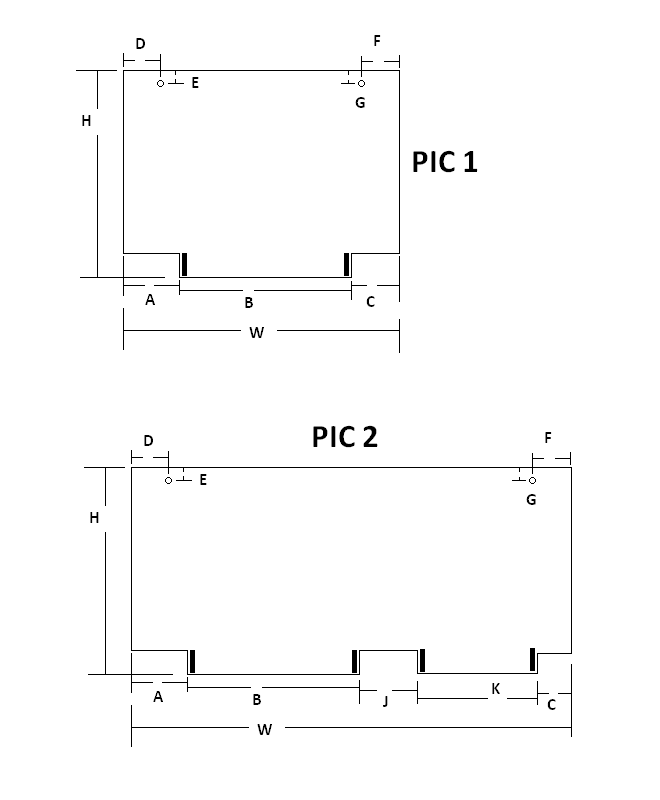
This page contains some information that I have collected while building a replica of the Moog Minimoog Model D. Please note that I make no guarantees about the accuracy of the information presented here. I have tried to make it as accurate as possible, but cannot be responsible for anything that may result from your use of this information. A great site for info on the mini is www.fantasyjackpalance.com Another great site for info on the mini is Kevin Lightner's www.synthfool.com In his docs section there is a lot of information on the minimoog. Here is some information on Minimoog pcb dimensions that I measured. You will also need these drawings. The front panel potentiometer that adjusts the amount of glide (R2) is called out as having a #1 taper. As I was able to buy a NOS Mallory pot with this taper I decided to measure it in case others are curious. Here are the results. Here is some information on the power consumption of my unit. The pcb replacement parts lists available on the web have a few mistakes. Here is a list of the things I have found so far. Here are some miscellaneous dimensions and other info: The front panel and other aluminum pieces on a unit I measured were 0.063" thick, except the back cover, which is 0.050" thick. The front panel aluminum is exactly 7" high. From the front of the front panel to the back of the bends at either end is ~0.4" The power supply pcb support standoffs are 3.15" apart, ctr to ctr. From the outside of the top panel left edge to the closest edge of the left standoff (from the rear) is 6 3/16" (6.19") . The top piece of the electronics enclosure is 26.75" wide, outside to outside. It's 2.45" deep. The bottom piece of the electronics enclosure is 3 7/16" (3.44") deep (front panel to outside edge of bent up part) From the back of the front panel to the back of the octave buffer bd is ~7/8". (This may vary, since this was a retrofit on some units) The rear cover top piece measures 1.62" from the front edge to the outside of the back panel. The side pieces on the rear cover measure 3.37" from the front edge to the outside of the back panel. The power transformer measures 2.2" high from the front panel to the top. It's 2.0"across, and 2.715" long (in dir of mtg screws). I think that the Moog power transformer is 30VCT at 300 mA. I am not positive about this. I am using Radio Shack 25.2VCT at 450 mA. So far so good. I plan to increase the two main filter caps to 2200 uF to reduce the ripple and provide a higher average voltage. The power transformer seems to be mounted on top of a piece of aluminum that is maybe 1/8" thick, or even a little thicker. At first I thought maybe this was extra support for the weight of the transformer, but I am thinking that it may simply be to allow replacing the transformer if necessary. All of the screw heads on the front side of the front panel are underneath the press-on front panel label, so it's not easy to access them. Probably the bolts that hold the transformer are attached to the extra aluminum piece, which is bolted to the front panel. Most front panel and connector wiring seems to be 24 awg solid core wire. This is easier to work with than stranded wire. I guess it held up OK to the bending every time the front panel was tilted up or down. The AMP DUO-TYNE connectors accept just one wire per contact, which explains why the power supply board outputs are fed back to the rectifier board for distribution. Also, three wires are routed from the contour pcb connector to the left hand controller connector, where they are tied together, but no connection is made to the left hand controller. I am using OP07 op amps instead of the 741's except for IC3,5,10, which must be 741's according to Kevin Lightner. Also using 1K SMT tempco's from Digikey (very inexpensive) mounted on the LM3046 chips. I have not done any drift testing yet, but intend to. |
|||
Copyright © 2007-2013 by Tauntek.com. All rights reserved.